
Building Elevations
- Landtech Surveys

- Aug 17, 2020
- 4 min read
Updated: Jan 11, 2023
Although as much as I enjoy land surveying, it's nice just now and again to get your teeth into something a bit different...and for me drawing elevations is just that. Ok I'll admit it, we are not normally asked to measure the facade of an early 20th century cotton mill...more often it's a standard 1950's three bedroom semi. But on this occasion I took it on myself to get up early one morning, before all the A6 traffic, and have a go at measuring one elevation and see what the results came out like.
So not wanting to travel to far afield, I stayed in my hometown of Belper in Derbyshire and decided that I would like to measure the south elevation of the East Mill. This Listed Grade II fortress like seven storey structure with its four corner turrets, Italianate tower and rows of windows was constructed by the English Sewing Cotton Company in 1912 in the destinctive Accrington red brick. It dominates the town and along with the North Mill, which was built in 1804, are part of the Derwnt Valley Mills that were given UNESCO World Heritage status in 2001. More recently the East Mill has become popular for bird watchers as it appears to be a favourite nesting spot for peregrine falcons. Not everyone has the same views of these beautiful birds though, as documented HERE on the BBC Website.

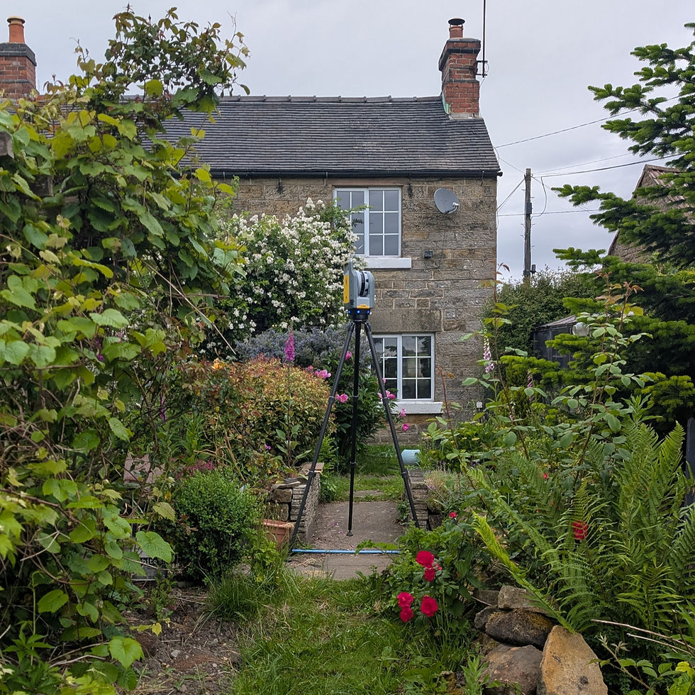
The survey instrument I am using today is the Trimble S7 Total Station. The S7 gives me the ability to measure directly and scan to the facade of the mill, and also take photo's using the vision imagery of the instrument.

After setting up the instrument I would first take some check measurement to certain points on the structure like the top of the turrets and random windows and doors. This is so that when all the information and data is transferred into Trimble Business Center (TBC) I can check the accuarcy of the images and resulting CAD linework. After taking my check shots I can now do an overall scan of the facade. The S7 is not equipped like a normal 3d scanner or like the Trimble SX10, but it will give you an overall spread of points on the facade to use later when back in the office. The closer the spread the longer it takes though, so I set my interval at 0.5m which didn't take too long but gave me plenty of points to work with. Next I took images with the instrument, roughly 50 in total. These images are used to create a panorama which will then be used to create the rectified images that will enable me to draw the elevation of the mill back in TBC.


It took me less than an hour to set up the instrument and collect all the data I needed on site. Next I processed all this data in TBC. The target here is to create Ortho-rectified images from 2d imagery collected in the field from the S7. I can use the vision imagery to create the 2d ortho-rectified images which can then be used for CAD geometry creation in TBC or exported to a CAD package or as an image.
I first need to create a plane in 3d space to drape these images onto to create the ortho-rectified image. For this elevation i need to create 3 planes, one for the left hand turret, one for the middle of the building, and another for the smaller right hand turret. These planes are created using points measured in the field and can either be DR shots, like the check points I had taken, or points from the scan data. I picked points from the scan data to create vertical planes which there were many to choose from.


The resulting images can be used in the cutting plane view in TBC and drawn over to create linework of windows, doors and other features on the building facade. This can then be seen from the station view of the instrument where the images were taken in the field. It's like having a live view of the scene with the CAD linework over the top. We can also view the linework in 3d, where in TBC you can see the difference in the planes used to create the linework for the facade.


All the linework here was created in TBC, I then exported to CAD for a final clean and to add some fills to the windows. I also added the ortho-rectified images to the background which I thought gave the drawing an interesting overall look.


If you feel that this is a service that could benefit you on your next project then please get in touch. We can measure floor plans and the elevations of houses, flats, shops, offices, churches, factories, industrial buildings, and even cotton mills!! We work nationally and will be more than happy to quote for any measured building surveys that you require.
#buildingsurveysderbyshire #buildingsurveys #buildingelevations #measuredbuildings #surveying #architect #architecture #planning #design #history #belper #derbyshire #eastmill #derwentvalley #UNESCO #mill #trimble #trimblevision #TBC


Comments